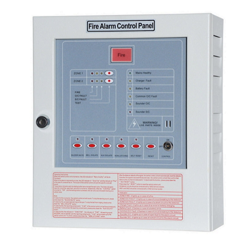
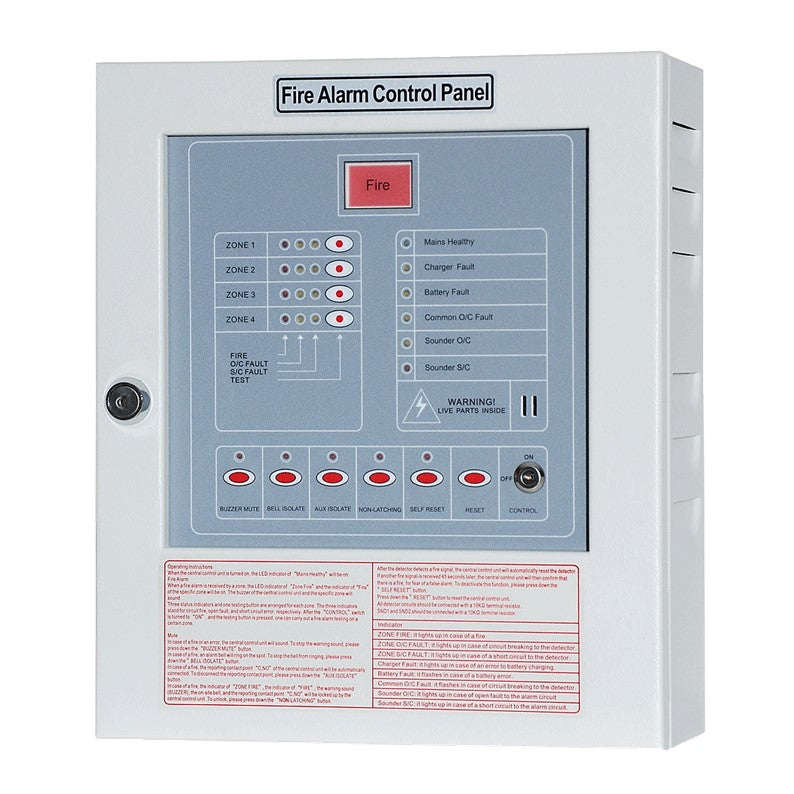
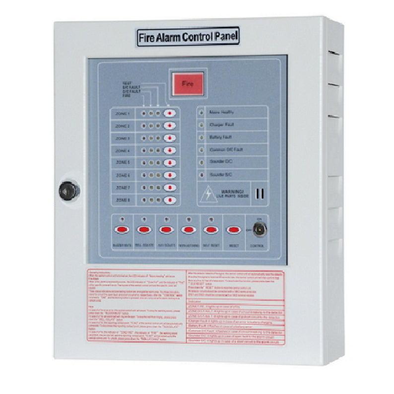
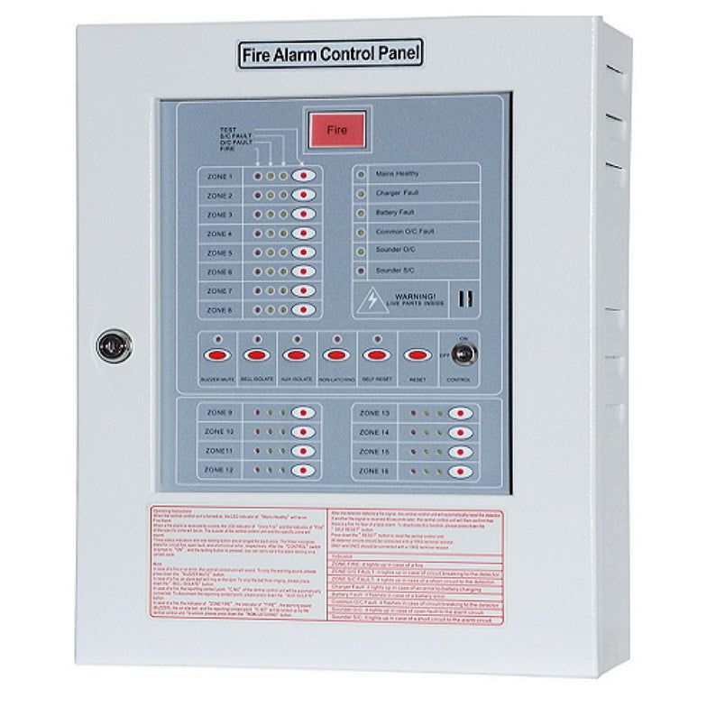
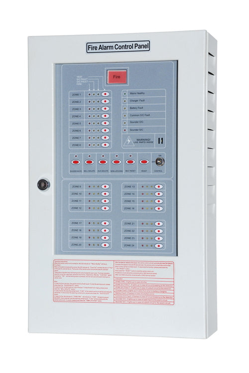
CM-P3 Fire Alarm Control Panel
Features
● Comprehensive circuit monitoring and corresponding indicators: each circuit is equipped with monitoring functions on fire, circuit break and short circuit, respectively
● The fire alarm circuit and the indicator circuit are able to detect circuit break and offer protection against short circuit
● The system always keeps close watch over battery charging and the voltage of the stand-by battery to ensure that the central control unit functions well in all circumstances to prevent any disaster
● Each circuit is equipped with a testing button to ensure the normal function of each monitoring circuit
● Key-controlled function switches prevent false alarms caused by accidental touch
● Digital detection of voltage error: whenever a voltage error is detected by the system, an error alarm will sound and an indicator will light on
● The system is equipped with a two-stage accumulation function to prevent false alarms. When the detector activates for the first time, the system will automatically reset the detector. If another signal is received later, the system will then confirm that there is a fire, for fear of a false alarm
● “Self-Protection” mode and “Non Self-Protection” mode are available to fire alarms
● Separate control switches: separate control panels for main audio, local audio, indicators, and reporting output
● There is a “Not-Located” indicator above each switch
● Digital-electronic switches are used due to advantages of dust proofing and a long service life
● A control panel with all necessary master indicators: the status of system alarm, power supply quality, and circuit connection are shown
● The alarm buzzer sounds in a loud voice: personnel in charge will be informed immediately in case of a firm alarm
● A large fire indicator: in case of a fire, a fire alarm will sound and the large fire indicator will flash
Specifications
| MODEL NO. | CM-P3 |
| POWER SUPPLY | 240V AC 50/60 Hz ± 10% |
| STANDBY BATTERY | 24V DC / Lead-Acid (Non-Spillable) Battery |
| E.O.L RESISTOR | 10 KΩ |
| EXTERNAL CIRCUIT | To-and -fro below 50 Ω |
| NO. OF BELLS | 1 time of panel circuits |
| CHARGING VOLTAGE & CIRCUIT | 26V DC below 450mA, Trickle Charging |
| CURRENT VOLTAGE | 24V DC operation voltage, below 5V 32mA |
| CHARGING CURRENT | 26.4V DC, under 450mA, Trickle Charge |
| DETECTORS | No limit of R.O.R or Fixed Temp. Heat Detector can be installed; Each circuit can connect to a maximum of 20 smoke detectors (standby current for detector: 24V DC 25 μA below). |
| NO. OF INDICATORS | 1 time of panels circuits |
| CASE MATERIAL | Standard Material of 1.2mm |
| REPORT CONTACT | No voltage N.O. contact Capacity 250V AC 7A × 2 sets |